BobCAD offers 12 different 3D tool path options that can be applied to surface solids or stl files. An experienced user will know the “personalities” of these cutting options and when to use which option and why, but as a new user this may not be as clear.
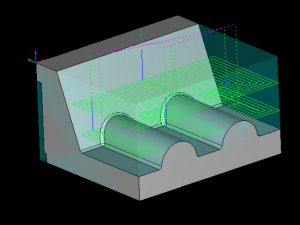
 In the photo below you can see a z level rough tool path. Based on tooling information from SGS they are recommending for a 4 flute 3/4 END cutting 6061 to use a SFM of 800 and a chip load of .004 WOC .1875 and a DOC 1.125 which is based on their formula of WOC= .25X D1 and DOC= 1.5 X D1
Using these settings you should feel confident you’ll your part will machine properly and with a good run time, right?
The cutting information is good, but would you plunge a 3/4″ end mill 1.25″ deep in 6061 to start your cut? I would think not – you would want your tool to start off the part and use the side of the cutter profile milling to use the settings SGS recommended. Checking all the options for Z level rough, you can’t figure out how to get the tool to start off the part so you choose to ramp option to get the tool down and into the cut.
You get the job done, but isn’t there a better way?


