

Machinists and programmers working with 3-axis parts generally need high-level control to generate efficient toolpaths. Developing toolpaths for these complex processes can be a huge undertaking when working solely on a CNC machine without supportive design and process software. The CAD-CAM software advantages speak for themselves in terms of the exponential increase in control offered. The BobCAD-CAM Surface Based Toolpath is a surefire control solution for 3D machining because…
 3D Surface Based Toolpaths Add Control
The BobCAD-CAM surface based machining feature empowers machine shops with advanced strategies for 3-axis programming.
Al DePoalo of BobCAD-CAM explains, “Surface based toolpaths are extremely powerful. They provide 3-axis programmers the control and confidence to machine those difficult jobs that many shops turn away. As a bonus, users who gain familiarity with these sophisticated strategies will shorten the learning curve if and when they make the transition to 4 & 5-axis machining.”
Advantages of Surface Based CAD-CAM
- High Level Control
- Reduced Cycle Times
- Mold & Die Machining Made Easy
- Advanced Machining Operations
- More Tool Options – T-Cutters, Dove, Tapered, & Lollipop
 “Working with surface based paths offers additional tool types and compensation. This gives you the power to drive t-cutters, dove mills, tapered cutters and lollipop tooling to machine undercuts or back chamfers and radii,” adds DePoalo.
Undercutting is generally a necessary aspect of 3D mold and die machining. The surface based machining operations are required for undercutting.
 Understanding Surface Based Toolpaths
Just because your CAM software can generate 3D toolpaths, doesn’t necessarily mean your system is surface based. If you’re unsure or if you’re not using BobCAD-CAM yet, your software may be converting the selected surfaces or solids into 3D meshes which your CAM system would be using to create toolpaths.
This is where users will notice the difference. Surface based toolpaths are generated using the surface data directly, without a conversion. The toolpath is generated based on the selected drive surfaces. The drive surface is the actual surface(s) that has been selected for the toolpath to drive along. The toolpath is driven based on the surface based toolpath strategy (7 options available) that was selected and the options you’ve chosen to work with. This is what gives the user the added control and superior advantages when working with surfaces directly. The latest version of BobCAD-CAM enables high level user control for surface based machining.
Users experience:
- Customizable Cut Tolerances
- Easy To Measure Cut Path Distances & Surface Handling Parameters
- Toolpath Segments That Can Merge
DePoalo points out, “The old saying of ‘use what you have’ holds true for many things, but complex 3D machining isn’t one of them. Without surface based toolpaths, there are a lot of jobs that just plain aren’t profitable to run, if you’re even able to run them at all. This is a huge reason why so many shops are upgrading to these high-end cutting strategies.”
BobCAD-CAM’s surface based machine toolpath operations include:
 Parallel Cuts
This toolpath is very similar to a planar or Z level finish strategy. The difference is in the control over the gaps in your surfaces.
“Not having to fill in surfaces that would otherwise cause the tool to drop down in cutting is a huge time saver,” says DePoalo.
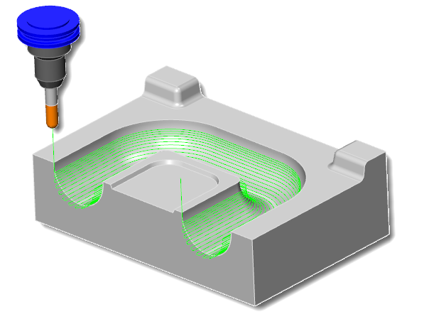
The parallel cuts feature creates a toolpath pattern with slices that are parallel to each other. The orientation of the slices are defined by two angles which include a machining angle in X-Y (which rotates the slices around the Z-axis) and a machining angle in Z. The geometry selection only requires a drive surface(s).

 Cuts Along Curve
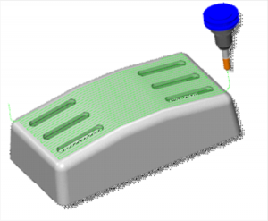
The Cuts Along Curve feature allows you to create a toolpath that is perpendicular to a lead curve (drive curve) on a selected drive surface. If the curve is a straight line, the cuts are created parallel to each other. You can either use a surface edge as the lead curve, or a curve that is on the surface. If the curve is not on the surface, then it’ll be projected onto the drive surface to create the toolpath.
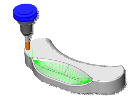
Morph Between Two Curves
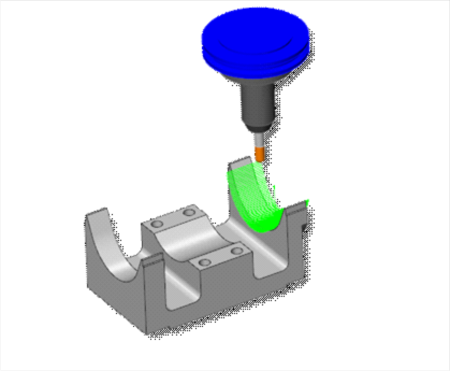
This is a feature that creates a morph toolpath between two leading curves. Morph implies that the generated toolpath gradually interpolates between the two curves and is evenly spread over the surface. This option is great for machining steep areas in mold making. When selecting the two curves, the geometry should be selected directly from the drive surfaces.
 Morph Between Two Surfaces
This cutting strategy works very similar to Morph Between Two Curves, the difference being your input geometry will be two surfaces instead of two curve boundaries.
“Morph strategies are very popular because the cutting paths generated follow the flow of the surfaces,” explains DePoalo.
The Morph Between Two Surfaces feature creates a morph toolpath on the drive surface, which is enclosed by two check surfaces. Morph means that the generated toolpath is approximated between the check surfaces and evenly spread over the drive surface. This is ideal for impeller machining with twisted turbine blades, but it’s also very useful for 3D surfacing. The main advantage is the option to compensate the tool to the drive surface and check the surface in the left and right corner of the work piece. This is accomplished using the tool radius, which is the distance (margin) between the tool center and the surfaces.
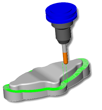
 Parallel To Multiple Curves
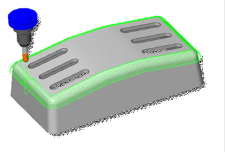
Selecting this feature allows the user to create toolpath segments parallel to a leading curve. The neighboring toolpath segments are parallel to each other. It’s important to point out that the cuts are not simply copied next to each other; instead, each new cut is an offset of the previous cut. When selecting the curve geometry, select the curves directly from the part. When using a single drive surface, you can only select a single curve from which to generate a parallel toolpath. When multiple drive surfaces are involved, you can then select multiple curves to use. Each curve is only used for the drive surface nearest to that curve.
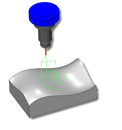 Project Curves
Project Curves enable the user to create projected toolpaths using either a user-defined geometry curve, offsets of that curve, a radial pattern, or a spiral pattern. When selecting curve geometry directly from a surface, the projected toolpath is identical to the original. When the curve geometry is above the surface, multiple results are possible depending on the scenario and parameter selections. This pattern can be used to create engravings as well as spiral or radial finishing patterns to complete surfaces.
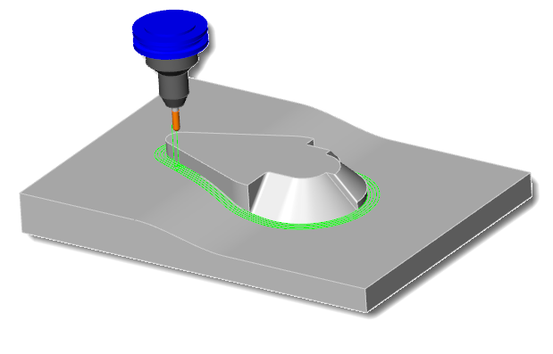
 Parallel To Surface
The Parallel To Surface feature creates cuts on a drive surface that is parallel to a leading surface. When selecting geometry, select the surface directly from the part. The advanced options for surface paths enables extended control over Morph Between Two Surfaces and Parallel to Surface. This option will only allow you to cut in front of a selected surface. This toolpath is similar to an offset style path where you defined the curve(s) from which the toolpath is offset.
DePoalo points out, “One of the advantages to this strategy is the ability to machine surfaces that go in multiple directions with a clean and consistent path parallel to your drive curve. Unlike a morph routine that follows the UV lines of a surface, parallel allows you to create a machinable path on complex surfaces that otherwise would result in tool motion that isn’t conducive to cutting.”
One of the advantages of this feature is undercut machining. Machining negative drafts using a t-cutter or lollipop is common practice with this toolpath. In addition, it can make selection easier because the input geometry is surface based, instead of using its sister toolpath, Parallel To Multiple Curves.
Using advanced surface based machining strategies can reduce cycle times and help your shop produce superior part finishes on every 3D job you do.
To learn more about surface based machining strategies or other popular or obscure CAD/CAM topics, contact BobCAD-CAM today at 877-262-2231 or 727-442-3554.
Click HERE to download a free trial copy of our most advanced CAM/CAM software to date.
Learn more about advanced surface based machining control in the link below: