In this example we are going to use a bmp file of a fish to:
• Get the profiles of the fish to use for the embossing process
• Use the image of the fish for texture
During the layout process we are going to use the following features:
• Load Image
• Rectangle
• Change image origin
• Line join
• Ellipse
• Spline fitted
• Deform contour
• Add new layer
• Offset
• Quick trim
• Arc sketch
• Line continuous
Getting Started:
Step 1: Draw a rectangle 11” X 6”
Step 2: Draw a center line
Step 3: Draw an ellipse 9.95” X 5”
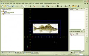
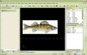
Step 4: Load Fish BMP
Step 5: Change the origin of the image to X: .95” Y: 1.25” Z: 0.0”
 Click here to see video |
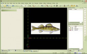
Now we are going to trace the body and fins of the fish:
Step 6: Add a new layer and make it active
Step 7: Use a fit spline to trace around the body of the fish
Step 8: Add a new layer and make it active
Step 9: Use fit spline & line continuous to trace around the fins of the fish.
 Click here to see video |
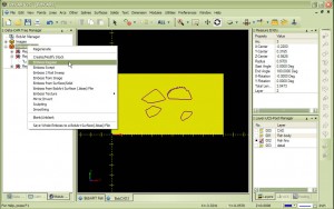
Now we are going to trace the gills and eye of the fish:
Step 10: Create a new layer and make it active
Step 11: Use the fit spline to create the gills
Step 12: Use arc sketch to create the eye
 Click here to see video |
Congratulations you have completed all the wire fame layout for this part!
The steps we will be taking now is for the emboss model, we are going to use the wire frame we created to raise and lower areas of our emboss model
Step 1: Create/ Modify stock X:11” Y:6”
Step 2: Emboss convex ellipse subtract the ellipse
Step 3: Emboss convex ellipse add the fish body
Step 4: Emboss convex ellipse merge high the fins
Step 5: Emboss line subtract the gills
Step 6: Emboss convex art the eye
Note: If you see a red X in the BobART manager it means that you have not “regenerated” the emboss model. To do this you RT click on emboss model and LT click on regenerate.
 Click here to see video |
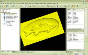
Let’s create our emboss model:
Step 7: Regenerate your emboss model
Step 8: Texture from Image
Step 9: Create a boundary for the image texture
Step 10: Smoothing
 Click here to see video |
|
 |
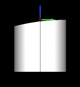 V25 has an awesome new stock wizard that can be used in so many different ways.
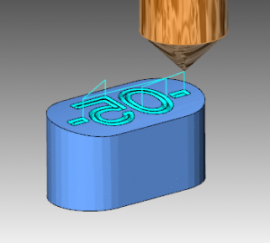
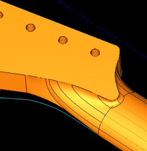 When it comes to surfacing with BobCAD you have lots of options but it’s not always clear what tools to use and why…. Today I had a chance to speak with Hugh about his guitar modeling projects and some of the challenges he was facing. After many attempts of creating a smooth transition surface for his prototype guitar Hugh had reached his limit.
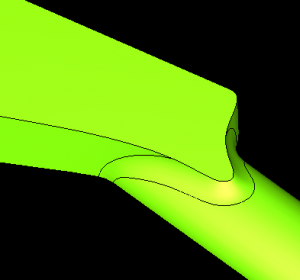 Hugh had been using lines and arcs to make up his wire frame. He did a great job of laying the profile out, but when it came to making this transition surface the results were faceted, and even bulged in different areas.


 Additional Features included:
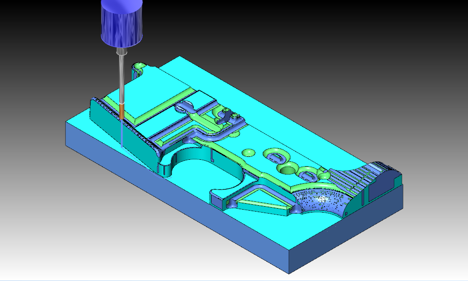
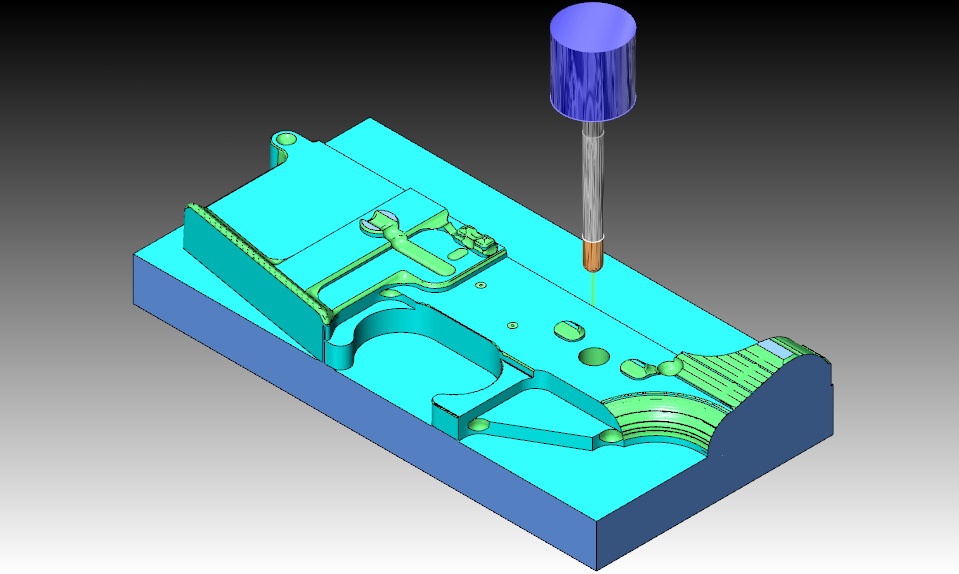
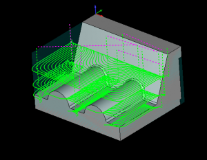 In additional the machine flat land option when checked will automatically identify flat areas of your part and machine them. Clearing stock that would have been left behind by our standard z level rough routine.
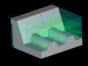 In the photo below you can see a z level rough tool path. Based on tooling information from SGS they are recommending for a 4 flute 3/4 END cutting 6061 to use a SFM of 800 and a chip load of .004 WOC .1875 and a DOC 1.125 which is based on their formula of WOC= .25X D1 and DOC= 1.5 X D1