


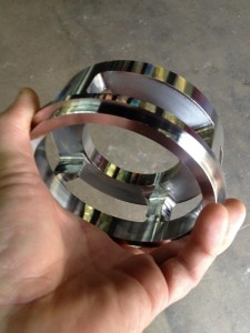
 This is a project I worked on with Ken, done on a 4th axis. The part came over as a print and needed to be drawn up flat. From there we used 4 Axis Wrapping to profile cut the “windows.” We went back and forth a few times on the post to get everything working right. I think Ken spent an all night running the job to hit the delivery date the next day. Nice little part and it was fun to work on.
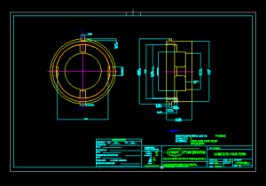
Using measure entity you can pick a line or arc and find out its properties. This is an extremely useful feature to find out the length of arc segments. Once you have the length of the arc segment to can lay the geometry out flat. In this example we were working off a 2D print, so it took a little extra work. If we would have started with a Solid we could have used the unwrap feature. That would have saved me a lot to time because the Unwrap will lay the work out flat automatically.
 The Unwrap function is used to create 2D wireframe entities by unwrapping cylindrical geometry. It can accommodate various part orientations – when the rotational center of the part is aligned directly on the X-, Y-, or Z-Axis, set the Unwrap Rotation Center Axis to the appropriate axis.
You can also draw a line through the rotational center of the cylinder to manually select as the Unwrap Rotation Center Axis. You select the line after selecting the unwrap geometry.
Another way to deal with custom part orientations is to use the User Defined option. When selected, the Origin and Direction groups become available. In the Origin group, type X-, Y-, and Z-values to define a point along the Unwrap Rotation Center Axis. In the Direction group, type the X-, Y-, and Z-values to define the direction from the Origin.