BobCAD CAM V25 has an easy to use and understand CAD interface that will allow you to design your parts from beginning to end quickly. V25 will allow you to import DXF, IGES, STEP, SLDPRT and many other files from external CAD systems. You can verify geometry and edit your drawings on the fly by using a wide range of simple CAD features. Toolboxes have been added to make access to frequently used CAD functions easy and fast. Whether you import the CAD file or draw it in BobCAD, you have the ability to create inspection reports and part prints will full dimensions. Basic drawing tools include working with splines, creating arcs through points, drawing points, lines, arcs, bolt patters, gears, sprockets and roller cams to name a few. BobCAD offers a complete wire frame surface and solid model designing package. Viewing your parts, rotating 3D geometry and verifying all your part data has been made easy all the way down to bring able to choose the drawing colors or screen background of your choice.
 Additional Features included:
Mirroring, Translate (move) and Rotating
Unlimited Undo/Redo, Cut, Copy & Past
Part Dimensioning
Multiple part viewing and rotation
Drawing with Points, Lines, Arc’s, Splines, Fillets & More
Complete Surfacing Tools
Complete Solid Tools
Verify Geometry, Trim Geometry, Layers and UCS
Milling:
BobCAD CAM is being used in a wide variety of shops for a wide variety of applications. This is due to the versatility of the program, customizable post processors, multiple cutting options and it’s ability to create fast accurate toolpaths and CNC code. Whether you’re doing 2D work or creating complex 3D parts programs, BobCAD-CAM allows you to generate accurate toolpath faster, smarter and easier for less money.
CAM Features Included:
Stock & CAM Wizard
CAM Job Tree
Multiple Machine Setups
Associative CAM
Tool Patterns & Machining Order Control
Tool Database, Cribbs, Arbors, Holders
Pre Defined Material Database
Speed & Feed Calculator
Save & Load Tool Path Setting
CAM Tool Paths Included:
2.5 Axis Drilling
2.5 Axis Profiling
2.5 Axis Pocketing
2.5 Axis Facing
2.5 Axis Chamfer
2.5 Axis Threading
2.5 & 3 Axis Engraving
2D & 3 Axis Plunge Roughing
3D Slice Planer
3D Slice Spiral
3D Engraving
3D Slice Radial
3D Z-Level Roughing
3D Z-Level Finishing
BobART Features:
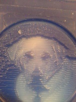
Turn Picture directly into 3D Embossed Models
Raster to Vector Conversion
Embossing
Texturing
Mirroring
Lettering
2 Rails Sweep
Sculpting
Smoothing
Productivity Features:
In addition to the many CAD and CAM features found in BobCAD CAM we have also added features that can only be found on systems costing thousands more. Our simulation software will simulate actual machine movements based on tool length, diameter, arbor & holder. Standard reporting tools for operations, run time, feed and rapid move length and stock left over. Giving you a complete view of how your part will be machined and if any tool path features need to be added or adjusted. Giving even the most novice of user the confidence to complete their programming and move on to the next project. In addition we included RS-232 communication for transferring you cnc files to the machine controller.
Training & Support:
With technical support services from BobCAD-CAM, you’re never on your own. We’re committed to your success long after your system purchase. Our technical support experts will help ensure smooth operation of your BobCAD-CAM applications day in and day out. 45 days of technical support is included for all new customers and is renewable thereafter for an annual fee. Assistance is provided by product and technical specialists trained to use and operate BobCAD-CAM products in a technical environment. Support for hardware or software systems on which BobCAD-CAM applications reside at the customer site is not included. Although troubleshooting an application in some cases requires us to ask questions regarding your operating environments. BobCAD-CAM support technicians are not responsible for network, operating system or computer maintenance.
Question: How much do you think this software is worth to your shop?

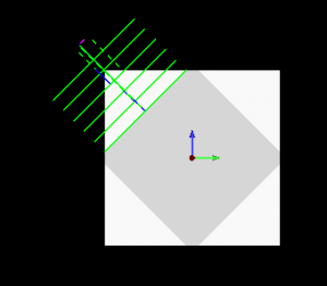
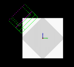
 V25 has an awesome new stock wizard that can be used in so many different ways.
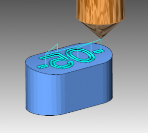
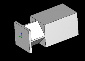
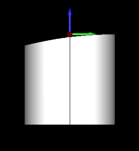
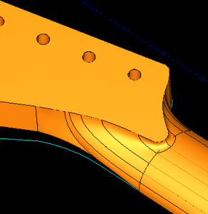 When it comes to surfacing with BobCAD you have lots of options but it’s not always clear what tools to use and why…. Today I had a chance to speak with Hugh about his guitar modeling projects and some of the challenges he was facing. After many attempts of creating a smooth transition surface for his prototype guitar Hugh had reached his limit.
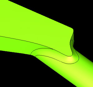 Hugh had been using lines and arcs to make up his wire frame. He did a great job of laying the profile out, but when it came to making this transition surface the results were faceted, and even bulged in different areas.


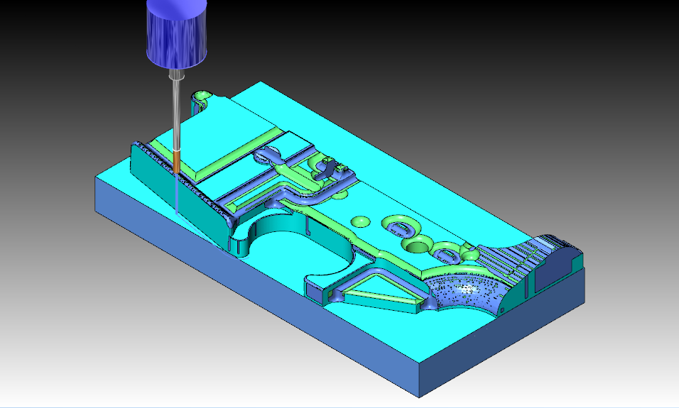
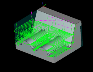 In additional the machine flat land option when checked will automatically identify flat areas of your part and machine them. Clearing stock that would have been left behind by our standard z level rough routine.
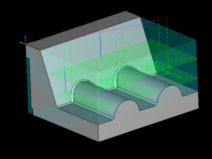 In the photo below you can see a z level rough tool path. Based on tooling information from SGS they are recommending for a 4 flute 3/4 END cutting 6061 to use a SFM of 800 and a chip load of .004 WOC .1875 and a DOC 1.125 which is based on their formula of WOC= .25X D1 and DOC= 1.5 X D1